Posted
Lately, I’ve been really into 3D printing along with asking myself what we can do with this technology now that it’s become, well, a technology. (At least, in the “this is a thing that can now be used, is robust, and is generally accessible to many people” sense of technology.) The first thing to print on a 3D printer is obviously another 3D printer, but, barring that, I started to ask myself what would be an interesting thing to print that would make some use of my previous fun experiences in photonics.
One might ask, “why photonics?” but the quick tl;dr is that most off-the-shelf pieces of optomechanical equipment are very expensive. (Also, messing around with lasers is cool.) So I gave myself the very basic challenge of building a Michelson interferometer with a very tiny budget along things I could easily get off of Amazon.
(And a 3D printer, of course.)
As a quick taste of the end result, below is a simple render of the final CAD assembly, along with the print and complete running set up.
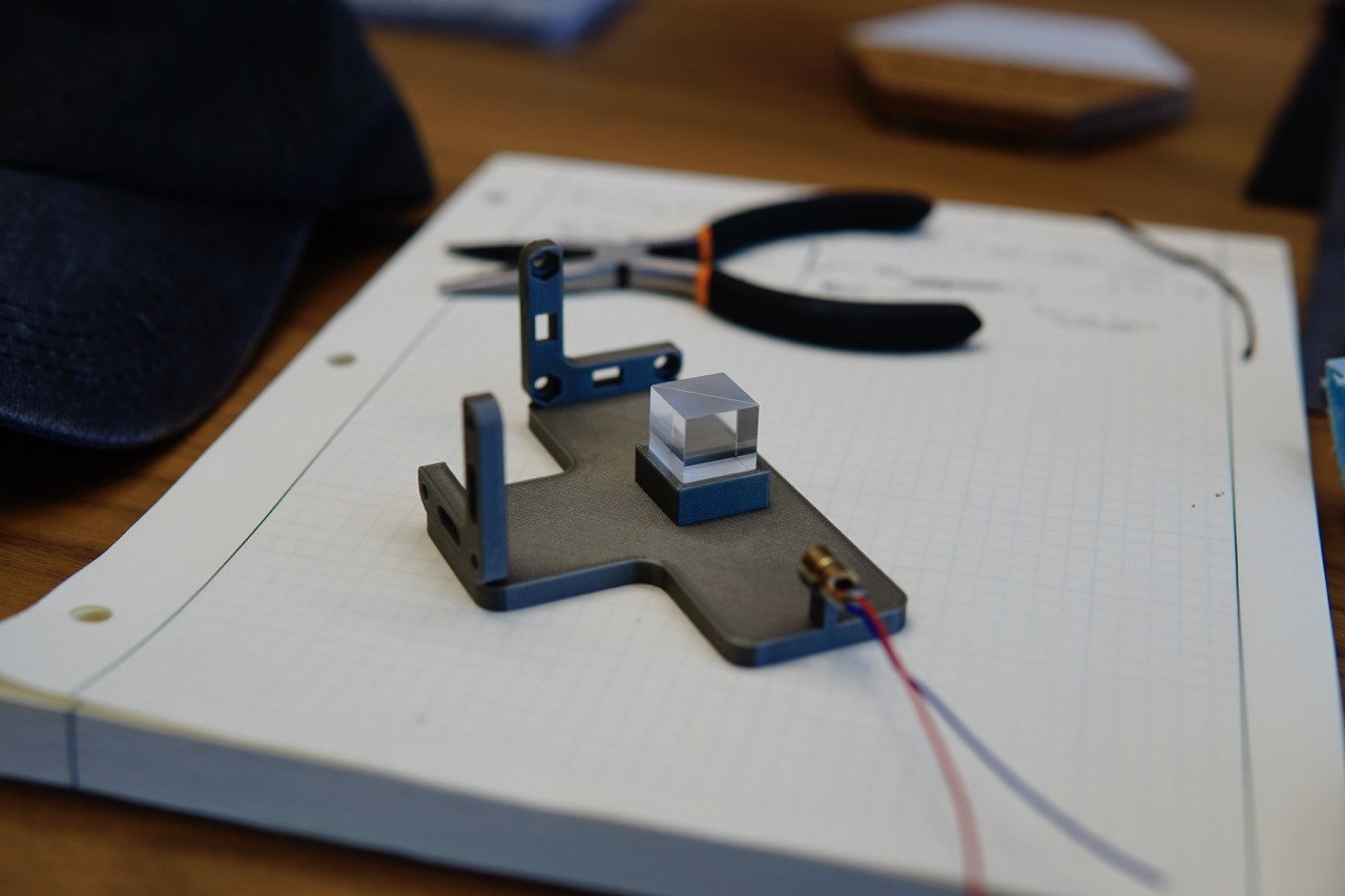
A picture of the build:

Running the actual interferometer after some basic alignment:

The output of the interferometer, after adjusting for exposure:

I will at some point put this up on Thingiverse or Printables but this’ll do for now. All of the CAD for this project was done in Python using build123d and the designs + step files are available on my Github CAD page.
What is a Michelson interferometer?
I won’t get too into the details, but the high-level idea of a Michelson interferometer1 is that it is a device for measuring very tiny changes in distance of a specific “arm” of the interferometer by using constructive and destructive interference.2
The rough layout looks like this:
                            ┌ ─ ─ ─ ─ ─
                              Mirror 2 │
                            └ ─ ─ ─ ─ ─
                     ┌──────────────────────┐
                     │                      │
                     └──────────────────────┘
                                 ▲│
                                 ││
            ┌───┐                ││
            │   │                ││               ┌─┐
            │   │                ││               │█│
            │   │             ┌──┼┼─┐             │█│
            │   │             │╲ ││ │             │█│ ┌ ─ ─ ─ ─ ─ ─ ─ ┐
┌ ─ ─ ─ ─ ─ │   │─────────────┼▶╲│▼─┼────────────▶│█│   Imaging plane
  Mirror 1 ││   │◀────────────┼──╲  │             │█│ └ ─ ─ ─ ─ ─ ─ ─ ┘
└ ─ ─ ─ ─ ─ │   │             │  ▲╲ │             │█│
            │   │             │  │ ╲│             │█│
            │   │             └──┼──┘             └─┘
            │   │                │
            └───┘                │
                                 │
                                 │
                                 │
                                 │
                                 │
                                 │
                                 │
                                 │
                                 │
                                 │
                               ┌───┐
                               │   │
                               └───┘
                            ┌ ─ ─ ─ ─ ┐
                               Laser
                            └ ─ ─ ─ ─ ┘
The two beams (split in the beam splitter—the little rectangle with a diagonal in the center) add or subtract constructively at the output, which yields fringes that are visible to the naked eye. These fringes will move as light from one of the arms of the interferometer takes a longer or shorter path. (This could happen, for example, due to putting a hot element near the path length, which in turn changes the refractive index of the air around it, changing the path length, and moving the fringes observed on the output plane.)
The build
The Michelson interferometer is, I think, a great first experiment in CAD + 3D printing + basic assembly and construction for a few important reasons.
First, the interferometer has relatively tight (but not infinitely unforgiving) tolerances. It is just fussy enough that it actually tests our ability to make fairly robust and adjustable mounts and parts, without needing to have it survive a huge range of temperature conditions. Making kinematic mirror mounts that are adjustable enough and robust enough for a Michelson is, I think, just on the edge of easily-ish doable with some thought, while not being totally trivial.
Second, most optics lab exercises (in the undergrad “optics lab” sense) usually make it with pretty fancy parts from Thorlabs as it’s usually more about teaching undergrads how to align lasers and some basic calculations than anything else. It would be very cool to make a dead-simple demonstration that anyone could make at home!
Third, Michelson interferometers are pretty much the ideal candidate for 3D printing as a whole assembly, since the only thing that generally needs adjusting are the mirrors, which themselves are adjustable by construction. Everything else (such as the laser mount, or beam splitter mount, or the imaging plane object) can just be 3D printed directly.
And finally (and probably most importantly, for someone who hasn’t really done CAD in many years): it’s a pretty simple thing to CAD!
Kinematic mirror mounts
The only “hard” part of the entire project was making the kinematic mirror mounts. These are made in two parts and require some screws, nuts, and some tension springs. (Also some rods to hold the springs, but you can print these too, if you don’t want to buy a kit.)
Here’s the kinematic mirror mount assembly, in parts:

The stage mount is the L-shaped object, which is the stationary part that we will assume is fixed onto the board. The mirror mount is the thingie with the square extrusion that is meant to have a mirror super-glued onto it.
The simple idea is that 3 points define a plane—in our case, the orientation of the mirror mount and, in turn, the mirror. To adjust these three points, we put 3 thumb-adjustable screws through the stage mount (passing through it with some nuts). The ends of these screws touch the mirror mount at three points in the back, forming the desired plane. Finally, we need some way for the 3 points on the mirror mount to stay fixed to the ends of the screws. One way people have done this is by using some permanent magnets, but these mounts are very finicky in practice. I instead took a page from here and used tension springs going through both the stage and mirror mounts to keep the mirror mount fixed to the ends of the thumbscrews.
Here’s an assembled version of it with all the nuts and bolts and such:

The CAD files and build123d code for just the kinematic mirror mounts is also available on my Github. Note that, to actually use it in, uh, real life, you’ll have to find some way to mount the stage somewhere in your design. (For example, you can mount it on a post with a screw at the bottom, like the Thorlabs mounts.)
Complete interferometer
Ok, the final BOM is pretty easy:
- 50g PLA (any color will do)
- 1x 650 nm diode laser (here’s the 30 pack I used from Amazon)
- 2x “craft” square mirrors (I used these from Amazon)
- 1x 50-50 beam splitter (I used this one from Amazon)
- 6x M3x10 thumbscrews (normal M3x10 screws will do in a pinch)
- 6x M3 nuts
- 4x 4x10mm tension springs
- 8x 4x10mm steel rods
The total parts cost, without the beam splitter, I think works out to well under 3 USD, even if you get the screws, nuts, springs, and rods from relatively expensive “variety packs” (like I did, to start).
Ok, time to confess: I did cheat a little in calling it the “cheapest” Michelson interferometer, since technically even this beam splitter is like 16 USD, but it is very possible to use a microscope slide instead at the cost of some contrast, which will net out to < 20 cents, even at pretty expensive per-unit prices.
But hey, the total BOM here is really < 3 USD then! If not, it’s less than 20, but you can reuse the expensive part (the beam splitter) for any other experiments you might run.
The assembly is pretty trivial once you’ve printed the parts, so I won’t go through it here. The print settings I used are:
- 15% infill (or whatever default your machine uses is probably good enough)
- no supports
- no skirts
- PLA
My guess is pretty much any reasonable material will work, since everything that needs precision is adjustable, so long as you can print it easily.3
If you’ve made it all the way down here, some bonus images.
Printing the interferometer:

A picture aligned with the beam splitter:

Iterations of the kinematic mount (the first being just a print of this one) sitting next to each other:

Anyways, happy new year to everyone!