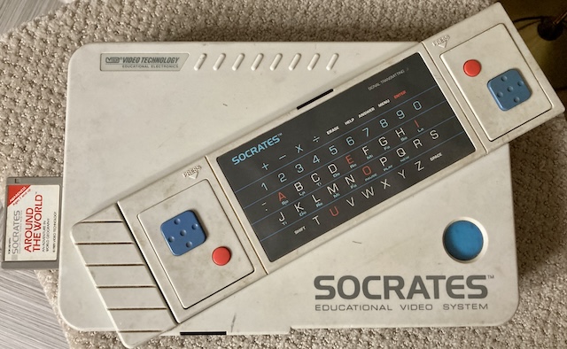
We’ve had a lot of fun with VTech’s computers in the past on this blog. Usually, they’re relatively spartan computers with limited functionality, but they did make something very interesting in the late 80s. The Socrates is their hybrid video game console/computer design from 1988, and today we’ll start tearing into it.
Checking it out
These machines are oddly inexpensive and plentiful on eBay. I suspect that, like most “educational” computers, they made way too many of these, selling them very cheaply in anticipation of big sales of cartridges to make a constant influx of cash over time. The classic razor-and-blades model. As a result, retail stores were allowed to slash the prices on seasonal sales, which flooded the market. Most of the boxes I see on eBay have two or three price tags stuck on top of each other, indicating they were certainly not bought at full MSRP.
As you might expect for an eBay transaction, my Socrates showed up late, completely filthy, and in a heavily-damaged, too-big box. Luckily, the Socrates is built of some pretty thick plastic. I spent a lot of time rubbing it down with wet wipes and paper towels soaked in Windex. I was not hopeful that the keyboard worked, as the sticker on top was wavy, which indicated water damage to me.

In photos, I thought the big blue thing was a power button. It turns out to be a window looking into an expansion bay with a male edge connector inside it:

This is apparently where you put expansion devices, such as the voice module. We’ll talk about that in a bit.
The back of the system has two coaxial RF jacks. One is for “Antenna In,” and the other is for “RF Out.” I guess they decided this would be simpler for the end user than putting the switcher/tap outside the computer like most systems do. This isn’t going to last long.
Disassembly
“Educational,” eh? The way I learn best is by taking things apart. That’s how I got kicked out of the military museum. And the grocery store.
This thing is held together by an insane number of screws! The top of the case has a crudely cut hole hidden under a sticker, just like the Precomputer did.

Lots of hot glue and masking tape, too. I’d like to say this is the first computer I’ve taken apart that had masking tape in it, but the NEC Bungo word processor had a bunch of it inside, holding the broken plastics of the printer together. Let’s call this the first factory masking tape.

There’s a weird rusty spot under the tape for this keyboard-IR-receiver cap.

I don’t think these capacitors leaked, not at this angle, but boy is that rusty spot ever suspicious. Am I going to ESR-test these caps? Absolutely not. We got stuff to do.

The motherboard is removed, showing that there really are not that many parts, which helps explain the low cost. Toshiba dominates as supplier, as they did with the VTech Precomputer when I looked into that a few years ago. You can see a much better scan of the Socrates motherboard on Wikimedia.
Key parts, from left to right:
- VTech mask ROM. 32-pin, so likely 1Mbit;
- Zilog Z84C0004PSC or Toshiba TMPZ84C00AP CPU (CMOS Z80);
- Dense QFP gate array VTEL 27-0769, a Toshiba TC17G032AF;
- Multiple Toshiba TMM41464AP-12 64K x 4 DRAMs;
- Toshiba TMP42C40P1844 4-bit microcontroller, probably for IR decoding because of where it’s placed;
- A huge number of passives, some of which are probably a DAC for generating colour video and audio.
It’s a shame that so much is integrated into that gate array, but this was an inexpensive machine and large-scale integration keeps costs way down.

Judging from the “24” on the edge connector, I expected the expansion port to be 24-pins. It’s 12 pins on the top of the console… and then a big blob of ground on the bottom. The motherboard PCB reveals that this connector goes “TO VOICE CARTRIDGE.” With so few pins, this is probably for simple I/O devices and unlikely to be useful as a full general-purpose expansion port, but you never know.
AV Mod
Blog superfriend Johnny Blanchard of Re-Enthused had already designed an AV mod for this machine in the past, so I asked him about it. He assured me that it was a very simple design, and so I decided to make it much more complicated.
One of the admitted flaws in Mr. Blanchard’s design was that the video output was pretty dim. A little bit of amplification never hurt anyone, and for that, I went to my standby: the TI THS7374 video amp.
To power that video amp, I added a 5-volt surface-mount LDO after discovering the RF module usually receives unregulated 12V from the rest of the system. The THS7374 really wants 3.3 - 5V, and feeding it twelve volts will blow it up. I know this from experience.
Since I wanted to show off a little bit, I initially used an extremely tiny, inexpensive LDO. After sobering up, I realized it would be extremely annoying to hand-solder. A SOT223 LDO was chosen to replace it – it’s not like I don’t have the board room – and I did a test print for alignment in the case. Everything fit well, so I proceeded to fabrication.

This PCB has all the hallmarks of being a really bad idea, from abusing commodity connectors in new ways to straight up using tape as a structural element.

Here are some of the many board-design crimes I committed here:
- Panel-mount RCA connectors are threaded through the PCB, then their ground ring is soldered up against a pad.
- The threaded connectors started to come loose from the locking nut as I heated them up, so I soldered the connector’s body against the pad, too. Hey, it’s good enough for Apple… too bad this is very poor strain relief.
- To make contact with the PCB, the “signal” part of those connectors are connected to the rest of the system by a length of wire soldered onto a surface-mount pad in probably the most strain-prone (and RFI-prone) fashion imaginable. I did some of the worst soldering in my life on this. I heat-shrinked the connector to try and hide it, but just made things worse.
- I marked the resistor R2 as “optional,” but didn’t include in the instructions what it did. It is a pull-down for the input video, but it would have probably been more useful if I had included two optional footprints, for implementing a voltage divider.
- There’s no positive physical mount inside the case to hold this PCB in place, because it’s much thinner than the old RF module. To fix this, I wedged the PCB up against the back of the case with two-sided 3M tape, which probably won’t hold long-term and provides even worse strain relief. I think a smarter idea would have been to do heat-set nuts of some kind through the case plastic (which, again, is mondo thick) although it would have been a pain to align it with the PCB. Hot glue, RTV, or a 3D-printed alignment shim is also an option to “finalize” this mod once it’s proven itself.

For my punishment, at least it was also very annoying to assemble. I made the RCA jack holes a little too big out of paranoia, so it was extra work to centre the thing while also trying to screw it down into a hole that was too big for the nut. Loctite would have helped a lot, except I only remembered that I had it after finishing soldering down both jacks.

A ribbon cable carries all the power and video information from the rest of the machine to the RF modulator. RF modulators are chunky and like to sink heat in general. As a result, I had a tricky time desoldering the old ribbon. The ground pins (2 and 4) did not want to let go of their position, and pin 3 frayed badly when it was being removed. All the hot glue that was holding the cable in place on the RF shield started to melt as well, contaminating the solder and making one heck of a stink in my shop.
After it was freed, I spent quite a bit of time trying to reform pin 3 back into a shape that could go through the new PCB. That’s something that I should have anticipated, and used bigger holes and better pin spacing to make easier on myself.
At last, we had an AV mod ready. Now it was time to find out if this filthy, untested toy computer actually worked. I decided to completely skip putting a scope on this, and instead decided to send it directly into a television set.
Power up
The Socrates takes 12-volt centre-positive power, so I dug out the RCA universal power supply I’ve used for a couple of projects. VTech suggests that you feed this sucker with a 850mA-capable supply. 10W feels like a lot for a system that mostly consists of a Z80 and some ASICs, but I’m not one to make things harder for myself. I reached for the “2500mA”-capable (we’ve proven previously that it is not) RCA universal power supply and fished through my bucket of universal tips until I found one that fit tightly enough that it wasn’t going to fall out.

The Samsung 910MP LCD TV is terrible at all composite video, so perhaps this wasn’t the best choice of testbed – it was hard to tell whether this ringing chroma is the system’s fault, my mod’s fault, or the TV set. That said, I’m not going to cry if the set explodes. And it didn’t explode, instead showing me this relatively decent-looking video. The audio was exceptionally loud and bleepy, which feels like it could do with a volume-limiting resistor or two. That can be someone else’s project.

Oh yes, little robot. We’re going to learn and play a whole lot more.
Actually Play It
To use the computer, I’d have to put batteries into the weirdo keyboard/controller combo device. Socrates keyboards interact with the system using infrared, and only infrared.
To power the keyboard, you need to insert four 1.5V AA batteries in this highly unusual Tetris-like configuration:

Electrically, it doesn’t make a difference, but it feels sort of like the keyboard was designed by space aliens. This decision was probably actually made for packaging reasons. I hoped that the negative terminal deep inside the keyboard wasn’t corroded from ancient batteries, because I couldn’t see it from outside, and plunked in a set of four Amazon alkalines.
Initially, I assumed that the switch on the back of the keyboard turned it on and off. They wouldn’t add it for no good reason. However, the “transmitting data” light flickered whenever I pushed a key in either mode.
To help figure out the switch mystery, I decided to open the keyboard up and take a look inside. Beware! The keyboard has different screw lengths, probably to compensate for the uneven clamping force of the hollow case. Make sure to pay attention to which screw goes where.

Unfortunately, the inside of the keyboard has this fragile-looking membrane attached to the PCB. My bravery ran out. As far as I can tell, there is no way to turn the keyboard off when the system is not in use, and it probably uses a capacitor to provide momentary power when a button is pushed, just like a TV remote. You’ll definitely want to take the batteries out when you’re not using it.
I could not find any information online about what the switch on the keyboard PCB does, although I’m sure that the manual – which, as far as I can tell, hasn’t been scanned – must explain it. Perhaps it switches between two encodings of the data to make up for background interference from another IR source?
It wasn’t all a waste, though: I was able to push out the gummed-up and very dirty game pads from the back of the keyboard. They are very nasty, but still seem to work. Let’s try a game.

Around the World, Around the World
As far as I can tell, the d-pad on the right controller is hard to press, and the d-pad on the left controller has an unfortunate bias towards diagonal motion. Still, I was able to wrangle it enough to start a game of Around The World, a cartridge which contains many sub-games. You just have to sit through this seemingly unskippable title screen animation first, where a plane lands slowly and then the robot (named Socrates?) appears.

I gave a couple of the modes a try. There’s one where you guess which continent various hand-drawn replicas of landmarks are, which I didn’t do well on. For some reason, it seems to have a strong bias towards Australian monuments.

I did much better at this general-purpose country quiz, where it asked you to figure out which country is involved in a factoid and then click on it with the d-pad. Often, I knew the country but could not find out which blurry squiggle it was on the map. I wonder how much of this game has changed since 1988, what with the collapse of the Soviet Union and all.
Maybe if I had grown up with this game, I’d be a United Nations diplomat now. I bet they can afford really good old computers. Good news for you, though: absolutely nobody pays me for diplomacy.
Let’s move on to cracking this cartridge open and figuring out how it works.
Pirate Cartridge

When opening the charmingly floppy-disk-shaped cartridge, the first thing I saw was… another RF shield. They were really paranoid about it if they were trying to insulate a mask ROM from producing unwanted interference.

When the RF shield is removed, the ROM is exposed. Like most other VTech products we’ve featured in the past, this is a Toshiba TC531xxx 1Mbit mask ROM. We know how to dump these ROMs from the VTech Precomputer exploration, but MAME already contains this ROM, and I don’t feel like desoldering it right now.

The underside of the cartridge PCB provides no surprises: a 36-pin edge connector. It does seem like the PCB left some holes for an even larger ROM in the future, which is a little unusual of a way to do it, but indicates to me that VTech had larger plans for the Socrates and wanted to save on PCB spins. Just like they did on the Precomputer, being able to reuse a PCB for more than one design means that they can save by buying in bulk.

I spent a half-hour taking measurements of the shell and PCB using a cheap digital caliper. Then I set about buzzing out the cartridge, using the known pinout of the ROM to guess what each pin on the edge connector did.
Unlike the Precomputer, I’m not looking to fully decode the cartridge slot, but just to get some software running on the system. Someone else is welcome to figure out all the control signals and build expansion hardware for the cartridge slot in the future.
| Pin | Function |
|---|---|
| 1 | Ground |
| 2 | Unknown |
| 3 | Unknown |
| 4 | Unknown |
| 5 | Unknown |
| 6 | D2 |
| 7 | D1 |
| 8 | D0 |
| 9 | A0 |
| 10 | A1 |
| 11 | A10 |
| 12 | A4 |
| 13 | A5 |
| 14 | A6 |
| 15 | A7 |
| 16 | A12 |
| 17 | A16 |
| 18 | +5V |
| 19 | A15 |
| 20 | A14 |
| 21 | A13 |
| 22 | A8 |
| 23 | A9 |
| 24 | A11 |
| 25 | A3 |
| 26 | A2 |
| 27 | D7 |
| 28 | D6 |
| 29 | D5 |
| 30 | D4 |
| 31 | D3 |
| 32 | Unknown |
| 33 | Unknown |
| 34 | Unknown |
| 35 | |
| 36 | Unknown |
This pinout is very similar to the Precomputer, which is entirely reasonable. I’ll update this pinout later if I find out more information. Note that this pinout is untested as a result.
Before I sent away to have a cartridge made, I decided I would at least try to get my own code running in the emulator first.
Pulling Apart the Cartridge’s Brains
It looked as if Around the World was already dumped in MAME; the Arcade Italia site had a listing for it, and you could play it on the Internet Archive. I had to dig around for awhile to find it; it turns out it’s not a ROM, it’s in the “Software List.” It was listed as 27-5013-00-0.u1 in the aworld.zip bundle, rolls right off the tongue.

I ran all the ROMs against vbindiff, trying to find commonalities in their header bytes. My hope was that I’d find some fixed signature that would tell the Socrates that a cartridge is installed, and where to jump into the code at. I found that all of the ROMs had identical bytes at position 0 and 2 ($c3 and $40 , respectively.) What about the byte in between? I had no idea…
By reading the MAME driver, I was able to determine that cartridges are mapped into the memory between $4000 and $7fff . This memory is, of course, bank switched, because we already know that cartridges are at least as big as 1Mbit. I opened the cartridge ROMs in MAME, running the debugger with my traditional watchpoint instruction:
wpset 4000, 3fff, r, 1, { printf "Read cart at %08x => %08x\n", wpaddr, wpdata; g }
This produced a big spam log of every time the emulator tried to hit the cartridge. From this trace, I found out that all the cartridges acted identically up to a point:
| Address | Reads out… |
|---|---|
| $7ff0 | $aa |
| $7ff1 | $55 |
| $7ff2 | $e7 |
| $7ff3 | $18 |
| $4000 | $c3 |
| $4001 | Varies, more below |
| $4002 | $40 |
So we know that the first four bytes read are some kind of signature. $aa and $55 are common sentinel bytes for “a device is actually at this address,” because their binary encoding is alternating ones and zeroes. Same goes for $e7 and $18 , which are the complement of each other. This is less a “signature” and more a check that the data bus coming off the cartridge is reliable, which would indicate that a ROM is attached. I do love how practical the VTech engineers tend to be.
After confirming the presence of a cartridge, the emulator would jump to reading from the cartridge at the offset defined by position $4001 . For instance, if that byte read $e7 , it would then start reading in more data from $40e7 .
I wasn’t sure if that meant it was executing code at those positions, or just reading in more header info, so I amended my watchpoint to include the program counter:
wpset 4000, 3fff, r, 1, { printf "PC = %08x: Read cart at %08x => %08x\n", pc, wpaddr, wpdata; g }
Once I did this, I found out that after reading the higher-memory values, the computer has already jumped to $4000 … $c3 is the Z80 opcode for unconditional jump, JP nn, which also explains the $40 as that would form the upper byte of the target address. I really gotta memorize these things.
So now we know how to make the Socrates run Z80 code from a cartridge. How do we build something for it? My first step was to try and figure out if the BIOS had some helper function for printing a string. A lot of the carts had what looked like sane ASCII strings in their ROMs, so I assumed that there was some kind of call that could be made to print them to the screen.
It seemed that strings were prefixed with their length, like in Pascal, so “SELECT AN ACTIVITY” would first have the byte $12 .
Finding Printf
Since I did this before I knew about the complex Lua scripting available in MAME, I found it very annoying to keep up with the page switching using just the debugger. Maybe there is an easy way to map “virtual” addresses to “real” ones right inside the debugger, but I have yet to figure it out.
After trying a few different ROMs until I could find one where the page-switching aperture was “just right” to have both the string and the BIOS calls mapped in at the same time, I figured out that the print routine seems to use $0d as a terminator on strings. 27-5045 (“State to State”) has a couple strings very early on, looks like starting at $0d0 offset.
I managed to figure out that the callsite that left the ROM and entered the BIOS before printing to the screen was at $2080 , so I wrote down in my little table that $2080 was probably their equivalent of printf. But I still didn’t know where the XY location was, or how the string was passed to it.
For the string pointer, I noticed that before calling into $2080 , the calling code was writing the string into a buffer at $f040 . I decided to breakpoint at the entry to $2080 , and then use MAME’s memory viewer to edit the string at $f040 before letting it continue. That worked:

Eventually, I was able to trap some code at $43e8 that was trying to read the string length, and then using ldir to fill an internal buffer with the contents of the string. The sentinel $0d was indeed used as the terminator for the filling of the buffer, which makes me wonder why they had the length at all.
By working backward in the listing, I determined that a pointer to $f0a9 was somehow involved. Its content got written immediately before the call to $2080 . Normally, that value is is $c84a . I set a breakpoint right before it was written and changed the value of the register feeding into it. My first attempt was to change it to $c000 , which made the string appear at the far left of the screen.

After some more tweaking, I figured out that $4444 sets it to roughly the centre of the screen. It seems to be “the pixel address for the top left of the string.” On top of that, it seemed like the string’s colour is based on some sort of tile-based palette, as moving the black string out of the bottom row of the screen turned it white.
Writing Code, Finally
With this information, it seemed possible to now build a hello world cartridge. I fired up my favoured z80 assembler, zasm, and wrote a quick program to test my theories.
Unfortunately, the program only sorta worked. The emulated Socrates did indeed load the header and jump into running code, but there was bizarre corruption in the cartridge that was loaded into memory.
If I open the MAME memory viewer, you can see what’s happening here.

At the system startup, there is a bunch of stuff loaded into the $4000 to $7fff range of memory that is supposed to be occupied by the cartridge.

By the time I get to my cartridge’s entry point (remember, only the above four bytes have been read from the cartridge ROM by this point) it now looks completely different, but only the first couple of bytes actually look like my program:

There’s a lot of $c3 and $03 nonsense in here, which seems to echo the start of the ROM. What’s going on?
I took a wild guess and looked at all the other ROMs. $c9 always followed the four bytes that were read from the ROM, but I would have expected MAME to catch that if it was important. Still, I added it anyway, and… that made things even worse as now the cartridge wouldn’t even load.
Confused, I decided to try and pad it out using the zasm .org pseudo. I ended up with a 64K ROM, which is not as large as the retail games’ 128kB ROMs. Now my code loaded completely into MAME and looked right. I’m not sure if this is a bug in MAME, an oddity of the Socrates page-switcher, or a bug in the Socrates BIOS itself, but it was definitely spooky stuff for a bit there, and it set me back for a few days. Let’s move on.
My next step was to change the volume levels for ch1 and ch2, as both of them are set to uninitialized SN76489 hum when the system starts up. This just took a write to $12 and $13 , as indicated in the MAME driver. Thanks, MAME driver!
Now, it was time to try and clear the screen, and then print a message. Figuring out where to call to print a message was easy, because we could watch for a string getting loaded. But if I just called the $2080 routine, I didn’t see anything change on the screen (except for the occasional couple pixels of lime green, that may have even been uninitialized memory.) More stepping through retail carts would be required. For now, I decided to focus on filling the screen with a colour and leave printing for later.
After some more poking, I realized that a lot of carts were setting the RAM page switching mode $04 and then writing to $8000 to $ffff to fill the screen. That write spans two pages ($7fff bytes), which made sense to me, so I cargo culted it.

One annoying thing is that the pages do not end on a clean row boundary. You can see that the pink starts partway through a line that is otherwise entirely yellow. That’s very annoying, but it shouldn’t be noticeable for a solid colour fill.
I noticed at this point that it wasn’t exactly “half” on each page, which makes sense as many of the BIOS functions seem to depend on globals and buffers above $f000 , even in this page mode.
Printing Education
I was wondering where the font came from, as well. At first I assumed it was the BIOS, but as time went on I began to wonder if the ROM was being accessed to fetch it. I broke in the print routine, set a watch for anything in the cartridge range, and then stepped out of the print routine, letting it run to completion. A lot of reads from the cartridge were made, mostly in the range from $7b26 onward, which seemed mysterious.
I wrote a quick tool to pop open the ROM and take a peek at it to try and understand if there really was font data stored here. The font characters I’d been seeing were, at the widest, about 7 pixels tall by about 5 pixels wide, which is not an especially convenient format for a byte-based system. I assumed they had to have some padding.
I ran this same test against my own ROM and found that it was taking wild pointers into my cartridge space to, I assumed, do the same thing. Lots of calls to ldir from strange $f000 -onward pointers. So there’s something in the user area that tells the print routine where to look for a font, and I had missed the part of the official cartridges that sets it.
Unfortunately, I kept getting turned around trying to figure out where things were, and after a couple days of beating my head against it, I abandoned the project of “getting printf to work” for now. I would say that being able to write pixels to the screen is a good enough achievement for now.
Conclusion
So we’ve managed to pick up an arbitrary educational computer off the side of the road, figure out its ROM pinout, make a composite mod for it, and draw pixels to the screen. Why am I still feeling dissatisfied? It’s because I don’t have printf working still.
Now that MAME has landed the Lua debugging tools, I plan to write some more functionality to help me figure out exactly what’s going on inside the Socrates BIOS, and how to call their print functions. Ideally, I would also like to build an ATTiny88-based flash cart for the system, so you could push code from a real computer for development.
Is the Socrates a cool system? I would say so: it’s not every day that you see a company build their own video logic, and it’s a good stepping stone for me to figure out just what was going on in the 90s.
Downloads
| Component | Link | Remarks |
|---|---|---|
| VTech Socrates composite video/AV mod board | leaded-solder/vtech-socrates-av-mod | |
| VTech Socrates flash cartridge | TBD | Contact me if you want to test and debug this |