
-
LiDAR: custom serial driver for LDRobot LD06, LD19 or STL27L
- CRC package integrity check
- Hardware PWM calibrated using curve fitting
- 2D live visualization and export (numpy or CSV)
-
Panorama: 6K 360° spherical map
- stitched from fisheye photos using Hugin Panorama photo stitcher
- constant camera exposure by reading EXIF data of automatic
- constant white balance by iterative optimization of color gains
-
3D Scene: assembly of 3D scenes from 2D planes based on angle and offsets
- sampling vertex colors from panorama
- Open3D visualization and export (PCD, PLY or e57)
- aligning multiple scenes using global registration and ICP fine-tuning
- Poisson Surface Meshing (very slow on Pi4, recommended to run on PC)
single scans, no registration, no post processing.
klick the images to open the pointclouds in Sketchfab.

Exterior Scan (colormapped Intensity)

Interior Scan (Vertex Colors)
-
LDRobot LD06, LD19 or STL27L LiDAR
-
Raspberry Pi HQ Camera with ArduCam M12 Lens (M25156H18, p.7)
-
Raspberry Pi 4
-
NEMA17 42-23 stepper with A4988 driver
-
Power Supply:
- v1: 2x 18650 Batteries (7.2V) with step-down converter
- v2: 10.000 mAh USB Powerbank with step-up converter
 Rev. 1 using 2x 18650 Batteries and Buck Converter
 Rev. 2 using 10.000 mAh Powerbank and Boost Converter
 angular resolution of LD06 (left) vs. STL27L (right)
LD06:
STL27L:
Scan duration: 12s initialisation 17s shooting 4x photos 1:24m scanning 0.167° x 0.18° 37s stitching, cleanup
 Breadboard Rev. 2
- UART Tx (yellow)
- PWM (white)
- GND (black)
- VCC 5V (red)
- LD06 UART0 Rx: GP15
- LD06 PWM0: GP18
- Power Button: GP03
- Scan Button: GP17
- A4988 direction: GP26, step: GP19
- A4988 microstepping mode: GP5, GP6, GP13
GY-521 (MPU 6060): Accelerometer, Gyroscope and thermometer
i2c adress: 0x68
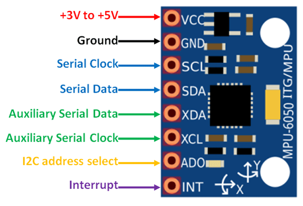
Since GPIO3 is hardwired to the Power Button, we need to use i2c-GPIO to map custom i2c pins (tutorial). Unlike serial is not getting crossed, so we connect SDA-SDA and SCL-SCL.
SDA: GPIO22
SCL: GPIO27
disable ic2_arm and enable i2c-gpio in /boot/firmware/config.txt
dtparam=i2c_arm=off
dtoverlay=i2c-gpio,bus=3,i2c_gpio_delay_us=1,i2c_gpio_sda=22,i2c_gpio_scl=27
search for devices on i2c bus 3:
# CPU fan at lower temp
echo "dtoverlay=gpio-fan,gpiopin=4,temp=45000" >> /boot/firmware/config.txt


# Power LED Heartbeat:
echo "dtparam=pwr_led_trigger=timer" >> /boot/firmware/config.txt
make script executable:
chmod +x gpio_interrupt.py
create new service for autostart
sudo nano /etc/systemd/system/pilidar.service
content:
[Unit]
Description=PiLiDAR-Button
After=network.target

[Service]
Type=simple
User=pi
Environment=LG_WD=/tmp
ExecStart=/usr/bin/python3 /home/pi/PiLiDAR/gpio_interrupt.py
Restart=no

[Install]
WantedBy=multi-user.target
reload daemon, enable and start service:
sudo systemctl daemon-reload
sudo systemctl enable pilidar.service
sudo systemctl start pilidar.service
check service if necessary:
sudo systemctl status pilidar.service
temporary solution:
sudo chmod a+rw /dev/ttyS0
sudo visudo
pi ALL=(ALL:ALL) NOPASSWD: /usr/bin/chmod a+rw /dev/ttyS0
then execute the temporary solution from python:
import subprocess
command = "sudo chmod a+rw /dev/ttyS0"
process = subprocess.Popen(command.split(), stdout=subprocess.PIPE)
output, error = process.communicate()
(TODO: check and remove old!)
- forget about
visudoand the subprocess call above. - Open a terminal and run the following command:
sudo nano /etc/udev/rules.d/50-ttyS0.rules - Write the following line in the file and save it:
KERNEL=="ttyS0",GROUP="dialout",MODE="0660" - Run the following command to check if your user is a member of the dialout group:
groups - If you see
dialoutin the output, you are already a member of the group. If not, run the following command to add your user to the group:sudo usermod -a -G dialout pi - Run the following command to reload the udev rules:
sudo udevadm control --reload-rules - Unplug and replug the serial device, or reboot the system, to apply the changes.
enable GPIO_18 (PWM0) and GPIO_19 (PWM1)
echo "dtoverlay=pwm-2chan" >> /boot/firmware/config.txt
check if "pwm_bcm2835" now exists:
Install RPi Hardware PWM library:
pip install rpi-hardware-pwm
install Hugin with enblend plugin
sudo apt-get install hugin-tools enblend
using uhubctl cli tool. install:
sudo apt-get install uhubctl
list all available hubs and devices
powering Raspberry Pi's USB-3-Ports (Hub 2) off / on
sudo uhubctl -l 2 -a off
sudo uhubctl -l 2 -a on
start jupyter for network access:
jupyter notebook --ip 192.168.1.16 --no-browser PiLiDAR.ipynb
 Housing CAD model Rev. 2
 FDM printing the old front panel (Rev. 1) in PETG
baudrate 230400, data bits 8, no parity, 1 stopbit
sampling frequency 4500 Hz, scan frequency 5-13 Hz, distance 2cm - 12 meter, ambient light 30 kLux
total package size: 48 Byte, big endian.
- starting character:Length 1 Byte, fixed value 0x54, means the beginning of data packet;
- Data Length: Length 1 Byte, the first three digits reserved, the last five digits represent the number of measured points in a packet, currently fixed value 12;
- speed:Length 2 Byte, in degrees per second;
- Start angle: Length: 2 Byte; unit: 0.01 degree;
- Data: Length 36 Byte; containing 12 data points with 3 Byte each: 2 Byte distance (unit: 1 mm), 1 Byte luminance. For white objects within 6m, the typical luminance is around 200.
- End Angle: Length: 2 Byte; unit: 0.01 degree;
- Timestamp: Length 2 Bytes in ms, recount if reaching to MAX 30000;
- CRC check: Length 1 Byte
The Angle value of each data point is obtained by linear interpolation of the starting angle and the ending angle.
The calculation method of the angle is as following:
step = (end_angle – start_angle)/(len – 1)
angle = start_angle + step*i
len is the length of the packet, and the i value range is [0, len].
using Web Visualizer Plotly to display 3D pointclouds works great in Jupyter.
Plotly seems to render client-sided, unlike Open3D Web Visualizer which renders host-sided and streams jpg sequences, which strains the Pi's both CPU and WIFI.
- Clone the Repo and run the installer:
cd /home/pi/PiLiDAR git clone https://github.com/LaserBorg/usb_dump --depth 1 cd usb_dump && chmod +x install.sh && ./install.sh "$(pwd)" - Create the config file:
echo '{"source_directories": ["/home/pi/PiLiDAR/scans"], "target_root_directory": null}' > usbdump.json
-
Check the log file:
-
to uninstall the service, run
chmod +x uninstall.sh && ./uninstall.sh -
if the mount point is still persistend after being removed, just delete them.
sudo rm -rf /media/pi/<your device name>
get CP210x_Universal_Windows_Driver.zip here:
https://www.waveshare.com/wiki/DTOF_LIDAR_STL27L#Software_Download
current bookworm version has deprecated sysfs GPIO interface removed.
use LGPIO as described here:
sudo apt remove python3-rpi.gpio
sudo apt update

sudo apt install python3-rpi-lgpio

# or in an env without system packages:
pip3 install rpi-lgpio
LGPIO creates temp-files (issue) like ".lgd-nfy0". gpio-interrupt.py executes 'export LG_WD=/tmp' to set it's CWD.
disable hardware acceleration for VS Code (source)
Preferences: Configure Runtime Arguments
Set "disable-hardware-acceleration": true
there is no wheel for arm64. build requires libxerces:
sudo apt install libxerces-c-dev
pip install pye57
sudo nano /etc/wpa_supplicant/wpa_supplicant.conf

# make sure country code is set:
country=DE
add entry to wpa_supplicant.conf
sudo wpa_passphrase "YOUR_SSID" "YOUR_PASSWORD" | sudo tee -a /etc/wpa_supplicant/wpa_supplicant.conf
inspirations
another Lidar implementation in Python
hardware PWM using GPIOZero
ICP implementations:
3D Demo Data for global registration, ICP, meshing etc.:
Using a MOSFET for switching: tutorial
A4988 Enable, Sleep and Reset tutorial