Last summer I received the very fun HackPack for my birthday. Every 2 months you get a box of parts and assemble a fun hardware project.
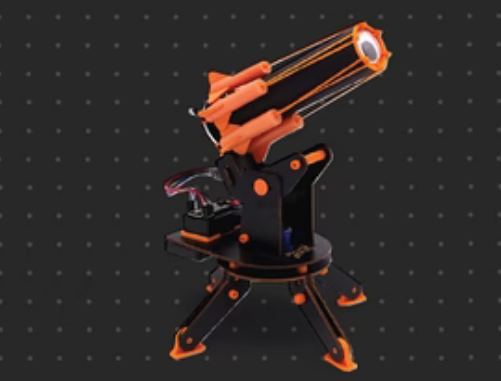
The first item in the pack was the IR turret. You control the turret with an IR remote, and can shoot the little foam bullets at things.

It was pretty cool, but I’m not a huge fan of shooting things. At around the same time I saw this XKCD:

I am into going outside to watch fun stuff happen outside, especially if it is when the International Space Station (ISS) is passing overhead. I also thought the XKCD device was a pretty fun idea.
After chatting with my friend Trevor at Plateau Astro, I figured I could hack the IR turret into something that points at the ISS at all times. He pointed me to this awesome project, where someone had done something similar.
What is the ISS
As a quick refresher, the International Space Station is a big habitable space craft that orbits the earth at an altitude of about 420km. It travels at a speed of ~28,000 km/h, and completes an orbit roughly every 90 minutes. There are astronauts living on the ISS, where they conduct cool experiments, and get to do things like strap themselves to walls in order to not float away while they are sleeping.
The best part about the ISS (for me), is that you can see it from earth! At night when it passes overhead, it looks like a very fast moving star, or a very very far away plane. You can download an app like ISS Detector, which will alert you to any visible passes. Once you get comfortable going out to look at the ISS, you can also start doing silly things like bouncing radio signals off it, or talking to the astronauts on board.
For motivation, here is the final product as the ISS passes directly over my house:
Pointing at the ISS
Our goal is to point an arrow at the ISS (without looking at a phone), so we know when it is above the horizon so we can see it. Given the design of the IR turret, we’ll need two angles: the azimuth and the elevation (or altitude).

We need a few pieces of information to be able to do this:
- The position of the ISS either now or some known time in the past
- Our current position and elevation
- And we need both of those to be in the same coordinate system
Finding the position of the ISS
NORAD tracks the position of satellites in earth orbit, and generates what is known as a Two-Line Element set, or TLE. The TLE is a standardized data format that describes an object’s orbital parameters, and from this data we are able to calculate the object’s position at some point in time. For objects in space like the ISS, the TLE is updated several times a day.
CelesTrak publishes these TLEs and makes them accessible to the public through their API in a format that looks like this:
ISS (ZARYA)
1 25544U 98067A   25093.13425953  .00020483  00000+0  37635-3 0  9994
2 25544  51.6367 318.7328 0004848   3.8316 356.2709 15.49192057503527
Since the ISS orbits the earth much faster than the TLE is updated, we need to calculate its current position based on the parameters in the TLE. To do this, we use the SGP4 algorithm to propagate the orbital elements of the ISS based on the initial conditions given in the TLE. The algorithm takes into account a bunch of things like the earth’s non-spherical gravitational field, the atmospheric drag, and the gravity of the moon and the sun.
Passing the initial conditions from the TLE through the SGP4 algorithm, we end up with a position based on Earth-Centered Inertial (ECI) coordinates, which is a plane fixed in relation to the stars at the time we are calculating for (the “epoch”).
We now need to convert our current position into the same reference frame (ECI) so we can then draw a vector from our current position to the current position of the ISS. This vector will give us the angles - azimuth and elevation, that we need to point our arrow.
  Direction calculateAzEl(double lat, double lon, double alt, double satX,
                          double satY, double satZ, libsgp4::DateTime now)
  {
    // Convert lat/lon to radians
    const double phi{lat * pi / 180.0};
    const double lambda{lon * pi / 180.0};
    const double h{alt};

    const double sin_phi{sin(phi)};
    const double N{a / sqrt(1 - e2 * sin_phi * sin_phi)};

    // Compute ECEF coordinates of the observer
    const double Xo_ecef{(N + h) * cos(phi) * cos(lambda)};
    const double Yo_ecef{(N + h) * cos(phi) * sin(lambda)};
    const double Zo_ecef{(N * (1 - e2) + h) * sin(phi)};

    const double theta{now.ToGreenwichSiderealTime()};

    // Rotate ECEF coordinates to ECI coordinates
    const double observerX{Xo_ecef * cos(theta) - Yo_ecef * sin(theta)};
    const double observerY{Xo_ecef * sin(theta) + Yo_ecef * cos(theta)};
    const double observerZ{Zo_ecef};

    // Compute the vector from observer to satellite in ECI
    const double dX{satX - observerX};
    const double dY{satY - observerY};
    const double dZ{satZ - observerZ};

    // Compute local unit vectors (East, North, Up)
    // Up vector (U)
    const double norm_O{sqrt(observerX * observerX + observerY * observerY + observerZ * observerZ)};
    const double Ux{observerX / norm_O};
    const double Uy{observerY / norm_O};
    const double Uz{observerZ / norm_O};

    // East vector (E)
    const double norm_E{sqrt((-Uy) * (-Uy) + (Ux) * (Ux) + 0.0)};
    const double Ex{-Uy / norm_E};
    const double Ey{Ux / norm_E};
    const double Ez{0.0};

    // North vector (N) = U x E
    const double Nx{Uy * Ez - Uz * Ey};
    const double Ny{Uz * Ex - Ux * Ez};
    const double Nz{Ux * Ey - Uy * Ex};

    // Project the satellite vector onto the ENU coordinates
    const double norm_d{sqrt(dX * dX + dY * dY + dZ * dZ)};
    const double dX_unit{dX / norm_d};
    const double dY_unit{dY / norm_d};
    const double dZ_unit{dZ / norm_d};

    // Compute ENU components
    const double E_comp{Ex * dX_unit + Ey * dY_unit + Ez * dZ_unit};
    const double N_comp{Nx * dX_unit + Ny * dY_unit + Nz * dZ_unit};
    const double U_comp{Ux * dX_unit + Uy * dY_unit + Uz * dZ_unit};

    // Calculate Azimuth and Elevation
    double azimuth{atan2(E_comp, N_comp) * 180.0 / pi};
    if (azimuth < 0.0)
    {
      azimuth += 360.0;
    }
    const double elevation{asin(U_comp) * 180.0 / pi};
    return Direction{azimuth, elevation};
  }
We end up with two angles:
- Azimuth: which is an angle in degrees from North
- Elevation: which is an angle in degrees from the horizon
Building the tracker:
Materials
- Arduino Uno R4 Wifi
- 28BYJ-48 Stepper Motor + Motor drive module (for the azimuth rotation)
- SG90 Micro Servo (for the elevation rotation)
- A 5V power source. I used the battery pack that came with the HackPack IR turret. It’s helpful if this is a battery to aid in cable management (more on that later).
- Misc wires.
- Sticky tack to put it all together…
Assemble the circuit like so:
![]()
The stepper motor is connected to pins 8-11, and the servo motor is connected to pin 12. I also wired in a switch, but that is optional.
The body
The original IR turret didn’t quite serve my needs as I wanted the elevation “arrow” to be able to rotate a full 360 degrees. I’d also never designed anything in 3D before and wanted to learn! While I was at the Recurse Center, there were many kind people who helped me through this process.
The body was designed in OnShape (document, STL of body, STL of arrow, STL of motor horn)

It was a fun process to design. I had to make very precise measurements, like this:

If you print all the STL files linked above, it should be pretty self-explanatory how it all fits together. The only part of the IR turret that survived was the “legs”. You could probably screw the “motor horn” into a piece of wood or other sturdy thing and it should work the same.
I stuck all the electronic components to the back in a somewhat arbitrary manner with sticky tack. If there’s ever V2, I’ll make more room for this stuff.
Assembly
 The stepper motor horn attached to the base. Apparently using pencil led as a lubricant works very well on 3D printed plastic! You could instead just screw the horn into a piece of wood or other stable base
 Front view. Top of stepper motor should point north when tracker is turned on
 Rear view. Electronics attached with sticky tack
 Side view of battery and switch
 Top view of pointer attached to servo
The Code
The codebase was really fun to write, and I had to learn a lot of orbital mechanics to get it to do what I wanted to.
To get it running:
- Start with the battery disconnected from the arduino
- Download the Arduino IDE v2.3.3 from GitHub. Later versions create larger binaries that are larger than the available program memory on the R4.
- Make a new version of arduino_secrets.h, and popluate it with your WiFi information and current position.
cp ./arduino_secrets.h.example ./arduino_secrets.h
- Flash it onto the Arduino.
- By default, the Debug flag in
src/Config.his set, which means it will print debug information to the Serial console. If everything went well, you will see it print out:- Wifi status
- The current TLE
- Then every second it will print the azimuth and elevation it thinks the ISS is currently at. You can validate that this is accurate with the ISS Detector app
- Once all of this is running correctly, you can disconnect the USB cable, and connect the battery.
- Before turning it on, you should set the tracker with the top of the stepper motor pointing North.
- Turn it on. After a few seconds, it should connect to your wifi network, and move the motors to point at the ISS.
- Every second it will now update its position. It is most impressive when the ISS is closest to you, as the relative angle is much larger.
- You can track other satellites if you wish, by changing this line to whichever NORAD catalog number you wish to track.
constexpr const char CATALOG_NUMBER[] = "25544";
Notes
- I used the SGP4 C++ library from here.
- One of the issues I ran into while trying to get this to run on the Arduino was that while I was writing it, the codebase was too large to fit! This was the first time I’ve had to think about the size of a compiled binary - the most frustrating part was figuring out that using a C++
stringstreamwas adding too much code to my binary. - Please reach out if you end up building one of these!