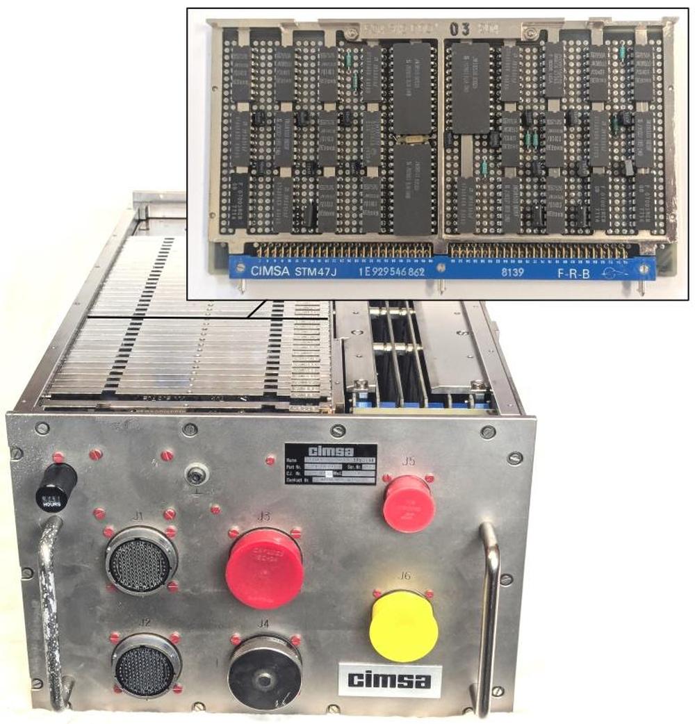
Spacelab was a reusable laboratory that could be carried in the cargo bay of the Space Shuttle, providing lab space for astronauts and experiments. Spacelab was controlled by a French-built minicomputer, called the Mitra 125 MS. Unlike modern computers, this computer didn't contain a microprocessor chip. Instead, its 16-bit processor was constructed from several boards of chips. In this article, I reverse-engineer one of the processor boards, shown below, part of the computer's Arithmetic/Logic Unit (ALU).

The Mitra 125 MS computer, built by CIMSA, with one of the ALU/register cards shown.
Spacelab consisted of a pressurized cylindrical laboratory that held experiments, computers, and work areas for researchers. A tunnel connected the laboratory to the Shuttle, allowing researchers to move between the Shuttle and Spacelab. Spacelab also supported up to five unpressurized "pallets" that were exposed to space, holding experiments such as telescopes and sensors. The illustration below shows the tunnel, the Spacelab laboratory, and a pallet installed in the Shuttle's cargo bay.1

Because Spacelab was a European project, it used a European computer, the Mitra 125 MS. The Mitra line started in 1971 when a French company called CII introduced the Mitra 15 minicomputer, a 16-bit computer that used magnetic core memory. Mitra is a French acronym2 that translates as "Mini-machine for Real-Time and Automatic Computing." As the name suggests, Mitra was both small and designed for real-time computing, making it suitable for controlling experiments. The Mitra 15 was a popular computer, with almost 8000 units sold.
In 1975, CII produced a successor called the Mitra 125. The Mitra 125 improved on the Mitra 15 by adding memory management, I/O processors, higher performance, and additional instructions. Spacelab used the Mitra 125 MS minicomputer,3 a militarized variant of the Mitra 125 that was produced by a company called CIMSA. A Spacelab mission had three of these computers: the Subsystem Computer controlled and managed Spacelab itself, while the Experiment Computer handled the experiments. A Backup Computer could take over if either computer failed.1 These computers were part of Spacelab's Command and Data Management Subsystem, which controlled experiments and collected data.4
The three computers were normally mounted in the Spacelab laboratory underneath the Work Bench Rack (details). The computers were controlled through a keyboard and a color CRT display, called the Data Display System (DDS). The computer installation and a DDS are visible in the photo below.
. The Spacelab computers were mounted under the Work Bench (right arrow). The Data Display System (left arrow) provided the interface to the computers. Photo is STS-51B Crew Portrait, 1984.")
For some Spacelab missions, the laboratory was omitted entirely, providing more room for experiment pallets. In this case, the computers were mounted in a small pressurized cylinder called the igloo. The researchers remained in the Shuttle, controlling experiments through two Data Display Systems that were mounted in the Shuttle's rear flight deck (photo).
The 74181 ALU chip
The Spacelab computer didn't use a microprocessor chip. Instead, like most minicomputers at the time, it was built from simple integrated circuits that were combined to implement the computer's circuitry. Unlike modern CMOS integrated circuits, these chips contained bipolar transistors, which were fast, but large and power-hungry, a technology known as TTL (transistor-transistor logic). Electronics hobbyists of a certain age will recall the popular 7400 series of TTL chips. The Spacelab computer was built from the military grade of these chips, the 5400 series.
The most complex chip in the computer was probably the '181 Arithmetic/Logic Unit (ALU) chip, containing about 170 transistors. The arithmetic/logic unit is the heart of a computer, performing arithmetic operations as well as Boolean logic operations. In 1970, Texas Instruments put a complete 4-bit arithmetic/logic unit on a single chip, called the 74181. Since the chip was fast, compact, and inexpensive, it was widely used, providing the ALU in computers from the popular PDP-11 and Xerox Alto to the powerful VAX-11/780 "superminicomputer".
The 74181 provides a full set of binary logical operations, including AND, OR, XOR, and complement. For arithmetic, it includes addition, subtraction, incrementing, and decrementing.5 Inconveniently, the 74181 doesn't support shifting right. Moreover, multiplication and division were much too complicated to be included in the 74181. Instead, a processor implemented multiplication and division through repeated addition or subtraction, combined with shifting. Likewise, floating-point operations were way beyond the capability of the 74181, but a processor could use the 74181 when performing the steps of a floating-point operation.
Although the 74181 only handled four bits, multiple 74181 chips could be combined to handle larger words, such as 16 bits or 32 bits. To handle carries, the chips could be chained together, with the carry-out from one chip fed into the carry-in of the next chip. This approach was simple but slow, since the carry had to "ripple" through all the chips before the answer could be obtained. The carry process could be sped up by using a carry-lookahead chip called the 74182, which speeds up addition by computing the carries from four 74181 chips (i.e., 16 bits) in parallel.
The Mitra's ALU/register boards
The Spacelab computer used eight '181 ALU chips to implement a 32-bit adder.6 (Specifically, these chips are the 54S181, a variant of the 74181: "54" indicates that the chips handle the military temperature range, and "S" indicates that the chip is built from high-speed Schottky logic.) However, the ALU boards required numerous additional chips. Depending on the instruction, eight different inputs could be selected for the ALU. Chips called multiplexers selected the desired value, requiring 32 multiplexer chips. Three 32-bit registers provided storage for ALU inputs and outputs, requiring 24 chips. Two 54S182 carry-lookahead chips provided fast carry computation. Finally, some simple logic chips (inverters and NAND gates) tied things together.
Due to the number of chips required, the ALU/register circuitry was spread across three boards, as shown below. (I reverse-engineered the board on the right.7) The '181 chips are immediately visible as they are much larger than the other chips; they have 24 pins, compared to 14 or 16 pins for the other chips. The first board has two '181 chips, while the last two boards each have three '181 chips. The last two boards are similar, but not identical.
 for a larger version.")
The three ALU/register boards from the Spacelab computer. Click this image (or any other) for a larger version.
Finding a 32-bit ALU was a surprise to me, since the computer is a 16-bit computer. The expanded ALU was probably implemented to improve performance. Multiplying two 16-bit numbers yields a 32-bit result, so a 32-bit ALU makes multiplication faster. Moreover, the computer supports 32-bit floating-point numbers, so the 32-bit ALU presumably makes floating-point operations faster.
The diagram below shows the architecture of the computer's 32-bit ALU system.
In the middle is the ALU itself, operating on two 32-bit operands: A and B.
At the left, multiplexers ("mux") select one of four values for A and one of four values for B.
At the right, the output of the ALU can be stored in three 32-bit registers, or sent to the rest of the computer via the bus. The first two registers are shift registers, allowing the value
to be shifted left or right, while the third register simply holds the value in flip-flops.
The first two registers are connected by buses to the rest of the computer, while the value of the third register can only be accessed by using it
for another arithmetic operation.8
I suspect that the shift registers are used for multiplication and division to shift the arguments at each step.

Block diagram of the ALU/register board.
The inputs to the multiplexers provide flexibility. For instance, you can add register 1 to a number from the bus, or
add register 2 shifted to the right to register 3.
(Note that this shifting is implemented by wiring the inputs to the multiplexer shifted left or right, completely separate
from the shift register's shifting.)
The "all 1's" input presumably acts as -1 in two's-complement, providing a decrement.
The B input can be taken from the bus, allowing the value to come from memory or from a general-purpose register.
The mix input is a jumble of signal lines, register bits,
a shift register input, and a pull-up with no apparent pattern.
I describe a few more mysteries in the footnote;9
presumably, the mysteries would be resolved if I reverse-engineered the whole computer.
The functions of the multiplexers, ALU chips, and registers depend on what instruction is being executed. Specifically, the computer's microcode engine generates control signals for the computer, including the ALU/register boards. Some of these control signals select which multiplexer inputs are used. Other control signals select the ALU's function. Finally, control signals select which register receives the ALU's output.
The board that I reverse engineered implements 12 of the 32 bits of the ALU and registers.
The diagram below shows the role of each chip on the board.
The three 4-bit ALU chips are indicated 2, 1, and 0.
Each ALU chip has two multiplexer chips to select the four A input bits and two multiplexer chips to select the four B input bits.10
Thus, there are 12 multiplexer chips on the board.
The three 12-bit registers A, B, and C are each implemented with three 4-bit chips.
Three hex inverter chips and a 4-input NAND chip complete the board.11

The ALU/register board with the chips labeled.
These printed-circuit boards (PCBs) have some interesting features. In most electronics, circuit boards have holes only where they are needed, but the Spacelab boards have holes in a fixed grid pattern. (IBM used similar boards in its System/360 computers in the 1960s.12) A hole can hold an IC pin or other component. Or a hole can be used as a via, connecting PCB traces on different layers. Another interesting feature of the boards is the vertical metal bars underneath the integrated circuits. These bars carry heat away from the integrated circuits.
The PCB traces are more visible on the back of the board (below). The traces are thin enough that two traces can pass between a pair of holes. Note the yellow "bodge" wires, correcting errors on the circuit board. I assume that these errors were fixed for the computers used in flight.

Back of an ALU/register board. This is a different board from the one I reverse engineered, since I wanted to show the yellow wires.
Each board has a 96-pin connector at the bottom, which plugs into the computer's motherboard. Note the three cylindrical pins sticking out of the connector. These pins are keyed to ensure that a board can only be plugged into the correct slot. That is, each pin has a metal tab oriented in one of six directions. On the motherboard, the connectors have corresponding notches. If the tabs and the notches don't match up, the board can't be plugged in.

A close-up of the connector, showing the keying. Also note that the zig-zag pin numbering on the left changes to an irregular number on the right. Unexpectedly, pin 52 is between pins 49 and 51, for example,
The boards in the Spacelab computer are dense, tightly packing integrated circuits to minimize the size of the computer. However, the boards are considerably less dense than American aerospace computers. In particular, the Spacelab computer used the same integrated circuit packages that were used in consumer electronics: through-hole DIPs (dual in-line packages with two rows of pins). In contrast, IBM's line of 4 Pi aerospace computers used "flat-pack" integrated circuits that were considerably smaller and thinner (details). As a result, IBM's double-sided circuit boards could hold 156 integrated circuits compared to 30 on a single-sided Mitra board of roughly the same size.
A brief history of the French computer industry leading up to this computer
Bull is one of France's earliest computing companies, created in 1931. Bull initially sold punch-card equipment, competing with IBM. By the 1960s, Bull was a major computer company with products such as the transistorized Gamma 60 computer, a large-scale mainframe that was said to be the first system specifically designed for parallel and multiprogramming. Unfortunately, Bull had difficulty competing with IBM, its stock collapsed, and Bull was acquired by General Electric in 1964, forming Bull-GE. The collapse and controversial takeover were a blow to the French computer industry, and the incident was dubbed the Affaire Bull. To make things worse, GE soon canceled two of Bull's computers, focusing instead on GE's computer line.
The Affaire Bull was not only an affront to French pride, but an indication that France was largely dependent on the US for computer technology. A second incident revealed the critical military consequences of France's weakness. In the early 1960s, France was attempting to improve its nuclear strength by develop a hydrogen bomb. The mathematics of fusion is computationally intense, so France attempted to buy powerful American computers: the CDC 6600 supercomputer and the IBM 360/92.13 However, the US government blocked the export of these computers to France in an attempt to limit nuclear proliferation.
These problems led French president Charles de Gaulle to decide that France needed a strong computer industry of its own. In 1966, he developed a plan for computing (Plan Calcul)14, where the French government would reorganize the computer industry, picking companies to lead in each sector from minicomputers to semiconductors.
In the minicomputer sector, the government created a company called CII by combining three French computer companies: SEA, CAE, and SETI. CII was primarily owned by a large French company called Thomson-CSF (now Thales).15 CII played a key role in the Spacelab computer, since CII developed the Mitra line of computers. In the mid-1970s, CII and the American company Honeywell merged, with the computer division spun off to form a new company called SEMS, with majority shareholder Thomson. Another Thomson subsidiary, CIMSA, focused on military electronics and produced the militarized versions of the Mitra line. In particular, CIMSA produced the computer for Spacelab.16
France's Plan Calcul is generally viewed as a failure. Despite expensive subsidies, the French computer industry remained weak and unable to escape American dominance. When Giscard d'Estaing was elected president of France in 1974, he ended Plan Calcul. There are various interpretations, such as the failure of government planning versus the free market, but my view is that in the 1960s and 1970s, IBM crushed most challengers in the computer industry, both American and foreign, so Plan Calcul didn't have a chance. As for Bull, the company went through a dizzying sequence of American takeovers and nationaizations by France.17 Just two months ago (March 2026), the company was reacquired by the French government.
Replacement by the IBM AP-101SL computer
Since Spacelab was a European project, using a European computer was a point of pride. Unfortunately, the French computers were eventually replaced by IBM computers due to performance needs and undoubtedly political factors.
During the Space Shuttle program, the computers on the Shuttle and in Spacelab became obsolete as computer technology rapidly advanced. Although the computers were originally considered powerful, their performance and memory capacity became problems over time. The Space Shuttle's IBM AP-101 computers were upgraded to IBM AP-101S computers, first flying in 1991. The AP-101S was half the size, three times faster, and had more than twice the memory, using semiconductor memory instead of magnetic core memory.
The Spacelab computer system needed a similar upgrade, and in 1991, the CIMSA computers on Spacelab were replaced with IBM AP-101SL computers. The AP-101SL was based on the Shuttle's upgraded AP-101S computer, but modified to support the Mitra's hardware architecture, instruction set, and I/O capabilities. The packaging of IBM's computer was slightly changed to match the dimensions of the CIMSA computer and to use an external heat exchanger rather than an internal heat exchanger.

The IBM AP-101SL Spacelab computer. The circuit boards are much larger than the original Spacelab computer boards or the original AP-101B boards. Note the flat-pack ICs on the boards. Photo courtesy of Kyle Owen.
Changing the Shuttle's 32-bit AP-101S computer to run the 16-bit Mitra instruction set was easier than you might expect, since the AP-101S already supported multiple instruction sets: a 32-bit instruction set derived from the IBM System/360 and a 16-bit instruction set called 1750A that was an Air Force Standard. Because the AP-101S implemented its instructions in microcode—low-level software that specified the steps of a machine instruction—the instruction set could be modified by updating the microcode.
I compared the circuit boards in an AP-101S with the boards in an AP-101SL to quantify the changes. The semiconductor memory boards and power supplies were essentially identical. The CPU boards had minor changes. Unsurprisingly, the I/O boards were completely different, and the complex I/O Processor (IOP) in the Shuttle's AP-101S was omitted. For more on the IBM AP-101 line, see my History of IBM's 4 Pi computers.
Conclusions
The Spacelab computer provides an interesting look at how computers were built before microprocessors took over. The components of a computer, such as the ALU, registers, and control circuitry, were constructed from simple chips. Since each chip didn't do much, the computer required 36 boards full of chips. Even so, the computer was compact enough to go into space. By modern standards, these computers aren't much—each computer had a memory capacity of just 128 KB of magnetic core memory—but they played a critical part in the space program.
I'm not going to reverse-engineer the full computer, but I may write some more about it. For updates, follow me on Bluesky (@righto.com), Mastodon (@[email protected]), or RSS.
Credits: Thanks to Steve Jurvetson for providing the Spacelab computer for examination.
AI statement: Despite the presence of the em dash, no AI was used in the writing of this article (details).