The morning of April 12, 1981, 20 years to the day after Yuri Gagarin became the first person in space, the Space Shuttle thundered into the Florida sky. Commander Young and Pilot Crippen were at the controls as the Shuttle ascended on its first flight. But the launch, like much of the flight, was really under the control of four computers in the avionics bays one deck below the crew. A fifth computer stood ready to take over in case of a catastrophic computer malfunction. These computers, Model AP-101B, were part of IBM's System/4 Pi family.
 and STS-40 (1991). Photo courtesy of RR Auction.")
Introduced around 1967, the System/4 Pi family was a line of compact, powerful computers designed for avionics roles. The military used these computers in everything from the F-4 fighter and B-52 bomber to submarine sonar systems and the Harpoon anti-ship missile. Other computers in the System/4 Pi family played more peaceful roles in the development of GPS and fly-by-wire flight controls. In space, System/4 Pi computers controlled Skylab, the first American space station, as well as Spacelab, the reusable laboratory flown by the Space Shuttle.
Despite the important roles of System/4 Pi computers, information on them is hard to obtain—Wikipedia entirely omits the CC, SP, and ML models.1 However, I received a stack of 4 Pi marketing brochures and articles, so I can now fill in many gaps in the history of System/4 Pi.
The first generation
The IBM System/360 line of mainframes was introduced in 1964. System/360 revolutionized the computer industry with the concept of one family of computers for all applications: business and scientific. The name symbolized that System/360 covered the full 360º of applications. The 4 Pi name extended this idea to applications in the 3-dimensional world: 4π is the number of steradians making up a full sphere. As IBM put it, "System/4 Pi also fills a sphere—the full spectrum of military computer needs—for airborne, space, or shipboard use."
Initially, the System/4 Pi family had three models: "Model TC (tactical computer) for satellites, tactical missiles, helicopters, and other applications requiring a very small, lightweight computer; Model CP (customized processor) for real-time computing applications; and Model EP (extended performance) for applications that require real-time calculation of very large amounts of data."2
The TC Tactical Computer
The TC Tactical Computer was a general-purpose digital computer, designed for low cost and medium-range performance (details). The TC had a 16- or 32-bit word, but used an 8-bit bus to reduce cost. It supported from 8 KB to 64 KB of magnetic core memory. It has a straightforward instruction set with 54 instructions in total, including multiply and divide. As was common at the time, it didn't have a stack for subroutine calls, but had a branch-and-store instruction instead. The original model ran 48,500 instructions per second. While this is appallingly slow by modern standards, it was mainframe-level performance at the time, comparable to a mid-range IBM 360/40 mainframe.

The TC was originally packaged in a briefcase-sized box (9.75" × 17.12" × 4.0") (below) that weighed 17.3 pounds, but it could be repackaged for different applications. For a tactical missile, the computer was implemented on semicircular circuit boards as shown above. The computer was constructed from TTL (Transistor-Transistor Logic)3 flatpack integrated circuits mounted on four-layer circuit boards. Two circuit boards made a sandwich around a metal structure that provided support and cooling; this three-layer assembly was called a "page". A page could hold about 300 integrated circuits, so the computer was very dense.

TC-1 computers played a critical role in Skylab, America's first space station, which was launched in 1973.4 The orientation of Skylab needed to be precisely controlled to aim its multiple telescopes. To avoid consuming propellant, Skylab was rotated by changing the speed of three massive gyroscopes, 155 pounds each. Two TC-1 computers controlled these gyroscopes, with one computer active and one computer as a backup. Each 16-bit computer had 16K words of storage that could be reloaded from magnetic tape or radio, and executed 60,000 operations per second. Each Skylab computer occupied 2.2 cubic feet (much larger than the briefcase-sized TC) and weighed 97.5 pounds. The Skylab computers are notable as the first fully digital control system on a crewed spacecraft.
The TC-2 model (below) was much faster (125,000 operations per second) and weighed 80 pounds. It was used for Navigation/Weapons Delivery in the A-7D/E attack fighter. In 1976, it was upgraded to the TC-2A, which was still faster (454,000 operations per second), supported more memory, and added 12 more instructions.
 computer.
Photo courtesy of Alex1970-14;
this computer is currently on eBay if you want it.")
Like most computers in its era, the TC used magnetic core memory; each bit was stored in a tiny toroidal core of lithium nickel ferrite, strung onto a grid.5 The core planes in the TC and other first-generation 4 Pi computers were about 6 inches on a side. With 16,384 cores in a plane, each plane held 16 Kbits. Thus, the 8-kilobyte memory in the TC required a stack of four core planes. A significant advantage of core memory was that, because it was magnetic, the data was preserved even when the memory was not powered. It was also highly resistant to radiation.
 core memory plane is the commercial version of the planes in the first-generation System/4 Pi computers.
Photo by José Luis Briz Velasco, CC BY-SA 4.0, cropped.")
_-_UNIZAR_-_Magnetic-core_memory_2Kbytes_IBM_360.jpg)
The CP Customized Processor
One step up from the TC series was the CP Customized Processor (briefly called Cost Performance).6 It used a 16-bit CPU, but had a wide 36-bit bus to memory for higher performance (including two parity bits and two storage protection 7 bits). Unlike the TC series, the CP series was (optionally) microcoded internally, so the instruction set could be easily customized.8 The CP system had completely different instruction formats from the TC system.10 The base model had 36 instructions and executed 91,000 instructions per second. The CP supported multiple addressing modes, more advanced than the simple addressing of the TC system. While the TC ran at 330 kHz, the CP ran at 2.4 megahertz. The CP's performance didn't improve as much as the faster clock would suggest, since both systems used slow core memory.

The IBM CP computer. from "IBM System/4 Pi Model CP" brochure, 1967.
One of the strengths of System/4 Pi was input/output, allowing it to communicate with external devices in real time. The CP-1 had extensive I/O capabilities: three high-speed parallel inputs, a high-speed parallel output, a serial output, 24 discrete input lines, 144 discrete output lines, and 24 interrupt lines. To support all these I/O signals, the CP-1 was packaged in two boxes: one for the computer itself, and one for the I/O interface. The CPU box is shown below; the I/O coupler box was similar, but the front sported over a dozen connectors for I/O lines. The CP-1 was used in the navigation/threat analysis system in the EA-6B Prowler electronic-warfare aircraft.9

The CP-1 computer, designated the CP-926/AYA-6. From "IBM System/4 Pi and Advanced System/4 Pi Computers" brochure, August 1973.
The CP-2 was the navigation/weapons delivery computer in the F-111 fighter plane, integrating radar and weapons. It was faster than the CP-1, perhaps because it was not microprogrammed, executing 150,000 instructions per second. It was also smaller, occupying one 47-pound box, although it had less I/O support. Unfortunately, this F-111 computer was said to be a disaster operationally because the computer had reliability problems and limited performance. The CP-2 was later replaced by the enhanced CP-2EX.

The CP-3 computer (below) was used for navigation and weapons delivery in the A-6E Intruder (1970) and other aircraft, replacing an earlier Litton computer with an unreliable drum memory. This computer could be integrated with laser-guided "smart" bombs. It was similar to the CP-2 and had the same performance, but had different I/O functions.

The CP-3 computer, designated the CP-985/ASQ-133. From "IBM System/4 Pi and Advanced System/4 Pi Computers" brochure, August 1973.
Like the TC, the CP was constructed from flat-pack TTL chips mounted on circuit boards called "pages". However, the CP used smaller pages with six layers instead of four; each double-sided page could hold up to 156 integrated circuits. Each page had two 98-pin connectors, reusing the style of connector that IBM used in Apollo for the Saturn V rocket's Launch Vehicle Digital Computer (LVDC). IBM standardized on this type of page for decades; the page below was used in the AWACS computer (1991) and is almost identical to the pages in the CP computer in 1967.

A standard IBM System/4 Pi page assembly. From "AWACS Data Processing Subsystem" brochure, 1991.
The EP (Extended Performance) computer
The EP was the most powerful of the original System/4 Pi computers. It was a 32-bit computer compatible with IBM System/360 mainframes, specifically the 360 Model 44.11 For input/output, the EP used the same I/O channel architecture as the System/360 mainframes. To support the complicated 360 instruction set, the EP was microcoded. It executed 190,000 instructions per second and weighed 75 pounds. Floating-point support was available as an option.

A multiprocessor version of EP, the EP/MP, supported up to three CPUs sharing memory. It was delivered for the Air Force's Manned Orbiting Laboratory (MOL), but the MOL project was canceled (details). The multiprocessor system was also used for the VS ANEW anti-submarine research project, part of the VSX program that led to the Lockheed S-3 Viking, an aircraft that used the System/4 Pi SP-0A computer instead of the EP.
The next generation: Advanced System/4 Pi
Early in 1970, IBM created the Advanced System/4 Pi family.12 These 32-bit systems were significantly faster, smaller, and more advanced than the previous System/4 Pi computers. These computers took advantage of improved integrated circuits, called Medium-Scale Integration (MSI). These integrated circuits held 10 to 100 gates per chip, compared to the earlier Small-Scale Integration (SSI) chips with 1 to 10 gates per chip, allowing a chip to implement a more complex function, such as a shift register, counter, or adder.) Moreover, these computers used faster core memory, reducing the memory cycle time from 2.5 µs to 1 µs.
This series originally consisted of three lines: Advanced Processor (AP), Subsystem Processor (SP), and Command and Control (CC). The AP line is the largest and most famous, powering the Space Shuttle as well as numerous aircraft. A few years later, IBM introduced the ML line. Although the SP, CC, and ML lines are obscure, they have some interesting features.
Advanced Processor (AP)
For the most part, the AP computers used an instruction set and architecture that was derived from the System/360, called MMP (Multipurpose Midline Processor).13 Unlike the EP computers, the AP computers were incompatible with System/360: the instruction format, the registers, the addressing modes, and the condition codes were different. Some AP computers used a 16-bit instruction set that was an Air Force Standard, called MIL-STD-1750A.
The Advanced Processor line started with the AP-1, a 32-bit processor that performed 450,000 instructions per second and weighed 36 pounds. It could be programmed in assembler or the military's JOVIAL language. It supported 16K halfwords to 64K halfwords of storage internally, and more could be added in an external box. It had four high-speed I/O channels, handling up to 15 devices per channel. Floating point was available as an option. The AP-1 is described in detail here.

The AP-1 computer, designated CP-1075/AYK. From "IBM System/4 Pi and Advanced System/4 Pi Computers" brochure, August 1973.
The AP-1 computer was used in the F-15 fighter for navigation/weapon delivery and data management. It was also used by Japan in the F-4 fighter. An upgraded computer, the AP-1R, had 256K of core memory and performed over 1 million instructions per second; it was used in the F-15E aircraft in 1983. The AP-1A was used in the development of the AWACS Seek Bus tactical communication system and the Joint Tactical Information Distribution System (JTIDS).
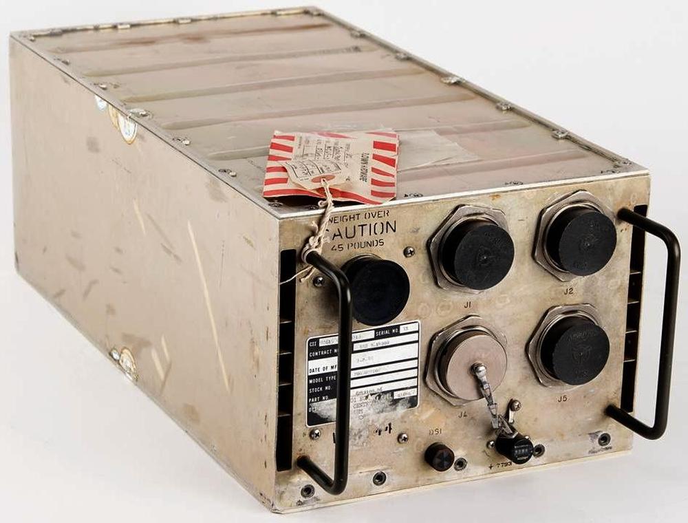
The AP-2 computer was almost identical to the AP-1 in appearance and functionality, with some changes to its I/O capabilities. It was used in the Central Integrated Test System (CITS) on the B-1 bomber to provide real-time testing and troubleshooting (details).
The AP-101 computer expanded the AP-1's instruction set from 83 instructions to 151, as well as having slightly faster core memory. The first nine AP-101 computers were used in NASA's digital fly-by-wire research program that used the F-8 fighter (link). The AP-101 was also used for GPS development.

The AP-101 computer. From "IBM System/4 Pi and Advanced System/4 Pi Computers" brochure, August 1973.
Around 1975, the AP-101B computer was developed for the Space Shuttle.14 The first step was improving the instruction set to support "high order languages" better, resulting in the AP-101A. Next, double-density core memory was used, creating the AP-101B that the Space Shuttle used for many years. The AP-101B computer was partnered with the IOP (I/O Processor), essentially a second computer that handled I/O, providing 24 data buses to the rest of the Space Shuttle. For reliability, the Space Shuttle had four redundant AP-101B computers that ran in parallel and voted on each output, so a faulty computer could be excluded. Moreover, a fifth computer was ready as a backup, using independently programmed software in case a software fault caused all four primary computers to fail.15
 and AP-101B computer (right). Photo courtesy of RR Auction.")
The Space Shuttle computer had 104K 32-bit words of memory. The AP-101B held ten memory pages (i.e., circuit boards), each holding 16K×18 bits, while the IOP held six pages, each holding 8K×18 bits.16 Although the memory was physically split between the two boxes, it acted as a unified shared memory.
 module stores 8K by 18 bits (details). This is a lower-capacity page, either from the IOP or from an early version of the AP-101. The page unfolds, with the core planes inside. Photo from klabs.")
The AP-101C computer (1977) had multiple improvements: quadruple-density modular core memory, upgraded logic technology, and repackaging to reduce cost.17 The AP-101C had 32K words of storage and ran at over 500,000 operations per second.18 The AP-101C was used in the B-52D Digital Bombing and Navigation System. It was also installed in the B-52G/H bomber as part of the Offensive Avionics System. The AP-101C was designed to survive radiation and electromagnetic pulse (EMP) hazards, with radiation-hardened circuits and parity in memory. Its "nuclear circumvention" feature resumed operation 50 milliseconds after a nuclear event, probably detecting a nuclear blast and quickly rebooting to avoid harmful effects such as latchup.

The AP-101C computer. From "IBM Model AP-101C" brochure, September 1978, retouched.
The AP-101C started the Modular Computer Series,19 which used 9"×6.4" pages, much larger than the previous pages. The MCS pages were modularized, supporting standard modules for CPU, memory, timing, power supply, testing, and a new military serial bus called MIL-STD-1553A. While previous computers were customized by changing the microcode in core-based Read Only Store (ROS), the AP-101C could be customized by changing PROMs (Programmable Read-Only Memories) and PLAs (Programmable Logic Arrays).
 page assembly. This page is from an AWACS computer, From \"AWACS Data Processing Subsystem\" brochure, 1991.")
A Modular Computer Series (MCS) page assembly. This page is from an AWACS computer, From "AWACS Data Processing Subsystem" brochure, 1991.
In the mid-1970s, the Air Force realized that the cost of developing software for complex military systems was a problem, partially because different computers had incompatible instruction sets. To solve this problem, the Air Force developed a standard 16-bit architecture and instruction set, releasing a standard called MIL-STD-1750A in July 1980. The Air Force made 1750A mandatory for future projects (unless there was a compelling reason not to use it), so many companies implemented computers that were compatible with 1750A. IBM developed a version of the AP-101 that ran the 1750A instruction set and called it the AP-101E.
The AP-101F (1982) was innovative in several ways. It was a dual-architecture computer that could support both the existing AP-101 instruction set (MMP) and the 1750A standard instruction set, providing a low-risk upgrade path. It was much faster, using a pipelined architecture that ran over 1 million instructions per second (MIPS). The AP-101F also used DRAM (Dynamic RAM) semiconductor memory, which was faster, denser, and used less power than core memory.20
Choosing semiconductor memory over core memory may seem like an obvious choice, but magnetic core memory had two significant advantages. First, core memory is nonvolatile: it keeps its contents when the power is off, so programs don't need to be loaded at boot. Second, core memory is resistant to nuclear radiation and cosmic rays, dangers that can easily flip bits in semiconductor memory. The volatility problem was solved by providing battery backup for the semiconductor memory. The AP-101F solved the radiation problem by using semiconductor memory backed up by "shadow" core memory. Later computers used semiconductor memory with error-correcting codes that could recover from flipped bits: each 16-bit word in memory had 6 additional bits for error correction.21 Because of the tradeoffs, some computers (such as the ML-1 discussed below) could use either core memory or semiconductor memory, depending on the application.
The B-1B bomber used eight AP-101F computers: one each for guidance and navigation, weapons delivery, controls and displays, critical task redundancy, preprocessor, and system test (CITS), while two computers provided terrain following (see Standards Application to B-1B Avionics Program). To minimize schedule risk, the B-1B initially used the AP-101C from the B-52, then transitioned to the AP-101D. Because of the need for a more powerful processor and pressure to use the standard 1750A instruction set, the B-1B moved to the dual-architecture AP-101F, gradually rewriting software from assembly to the standard JOVIAL language.
Shuttle redesign: the AP-101S
The most unrelenting enemy of a military computer is Moore's Law. Even if you start with a cutting-edge computer, it can take a decade for an aircraft to enter service, and then the plane may be flown for decades. Meanwhile, commercial computers become more than an order of magnitude more powerful every decade. The result is that military computers are constantly fighting obsolescence.
Space computers have the same problem: the Shuttle's AP-101 computer was developed in 1972 but the Shuttle didn't fly until 1981, making the Shuttle computers obsolete from the start. To improve performance, IBM started redesigning the computer the next year, creating the AP-101S. It executed 1.27 million instructions per second (MIPS), three times as fast as the AP-101B. However, this performance increase was nothing compared to the improvements in microprocessors. In 1991, when the AP-101S first flew, a Motorola 68040 microprocessor executed 44 MIPS, leaving the AP-101S in the dust. By the time the Shuttle program ended in 2011, an Intel Core i7 processor provided a blistering 100,000 MIPS. Astronauts had to use laptops to make up for the lack of computational power in the main computers; one flight carried 18 Thinkpad laptops.

The AP-101S with its cover removed. This is a prototype; the green boards on the left are likely development boards instead of the I/O boards that are normally in these positions.
Despite its lack of absolute performance, the AP-101S was a substantial improvement over the earlier Shuttle computer. The AP-101S fit the functionality of the AP-101B computer and the IOP (I/O Processor) into one box instead of two, saving 60 pounds. With five computers on the Shuttle, this change freed up 300 pounds for payload. As well as tripling the speed, the AP-101S was more reliable, had 256K words of memory instead of 104K, and used 100 watts less of the Shuttle's limited power. The AP-101S remained plug-compatible with the old computer and could run the same software, making upgrading straightforward.
 for the 36-bit \"fraction\" ALU. Much of the logic uses FAST (Fairchild Advanced Schottky Technology) TTL chips for improved performance. The board is covered with brown conformal coating to protect it from the environment. Click this image (or any other) for a larger version.")
One of the CPU boards from the AP-101S, specifically the CPU1 board. If you look closely, you can see "bodge wires" that correct errors on the board. The nine large ICs in the center are four-bit arithmetic-logic unit chips (74F181) for the 36-bit "fraction" ALU. Much of the logic uses FAST (Fairchild Advanced Schottky Technology) TTL chips for improved performance. The board is covered with brown conformal coating to protect it from the environment. Click this image (or any other) for a larger version.
Like the previous processors, the CPU of the AP-101S was constructed from multiple pages of TTL chips. Unlike the earlier AP-101B, the AP-101S used large "MCS" pages, as shown above. The diagram below illustrates how the upgraded AP-101S computer was formed by combining the pipelined CPU22 from the high-performance AP-101F, the I/O Processor from the original Shuttle computer, and the semiconductor memory from the AP-102 (discussed in the next section).23
 for a larger version.) From \"A New Computer for the Space Shuttle: The AP-101S General Purpose Computer (GPC) Upgrade\", IBM Technical Directions, 1986.")
The upgrade path for the Space Shuttle computer. (Click this image (or any other) for a larger version.) From "A New Computer for the Space Shuttle: The AP-101S General Purpose Computer (GPC) Upgrade", IBM Technical Directions, 1986.
The Shuttle could carry a space laboratory called Spacelab (completely different from Skylab) in the cargo bay to provide a spacious research environment. Spacelab had independent computers from the Space Shuttle, originally French-built CIMSA 125 MS computers.24 In 1991, these Spacelab computers were replaced with IBM AP-101SL computers.25 The AP-101SL was compatible with the 16-bit CIMSA computer, so it could run "Experiment Computer Operating System" and other Spacelab software without change.

Internally, the Spacelab AP-101SL computer is very similar to the Shuttle's AP-101S. It has fewer boards than the AP-101S, since it doesn't include the Shuttle's IOP (I/O Processor). The processor boards, the semiconductor memory,26 and the power supplies are nearly identical to the Shuttle computer, while the I/O boards are different.27

The AP-101SL with the cover removed. Photo courtesy of Kyle Owen.
AP-102 and VHSIC
Going back to the mid-1980s, IBM introduced the AP-102 computer. By 1992, it had become the most popular of IBM's avionics processors, with 1000 units sold. The AP-102 was a technological jump compared to the AP-101 since it used two VLSI (Very Large Scale Integration) chips, each containing 12,000 gates: one chip implemented the Instruction Processing Unit and the other chip implemented the Extended Arithmetic Unit (fixed and floating-point multiplies and divides). These chips were implemented with 2 µm NMOS technology. The AP-102 used CMOS static RAM for storage, which was much denser than core memory and used a tenth of the power. Because CMOS RAM loses its contents without electricity, the AP-102 used battery backup, lithium thionyl chloride cells that could power memory for up to seven years.
.")
The AP-102 computer. From IBM Technical Directions, 1985 (cover).
The AP-102 was compact, half the width of an AP-101.28 It weighed 20.8 pounds and used 95 watts. It ran the Air Force's standard 1750A instruction set, executing over 1 million instructions per second. The AP-102 was used in many aircraft in the late 1980s, including the stealth F-117A Nighthawk fighter, the MH-53J Special Operations helicopter, the F-4's Navigation & Weapon Delivery System (AN/ASQ-203), an "unspecified gunship", and a classified application.
A few years later, the AP-102 was upgraded with a new technology called VHSIC. If you've programmed an FPGA (Field-Programmable Gate Array), you've probably used the Verilog or VHDL languages. VHDL turns out to be a nested acronym, standing for VHSIC Hardware Description Language, where VHSIC stands for Very High Speed Integrated Circuit. But why this strange name?
In 1980, the Department of Defense started a billion-dollar program to help the US military keep its technological lead over the Soviet Union. This program, the Very High Speed Integrated Circuit program, was intended to get advanced, state-of-the-art integrated circuits into military usage faster. IBM was one of the contractors that developed these VHSIC "superchips." IBM created the V1750 processor, a radiation-hardened chip that ran the standardized Air Force instruction set, 1750A.29 This CMOS chip was built with 1 µm features, advanced for the time, and ran at 3 MIPS (million instructions per second).
The AP-102 mission computer was upgraded around 1992 to use the V1750 processor, resulting in the AP-102A. With the V1750 processor, IBM fit the CPU and memory onto a single card, a drop-in replacement for six cards in the existing AP-102. The result was up to 16 times as much memory and a factor of 3 improvement in performance, along with improvements in reliability, weight, and power consumption.
Subsystem Processor (SP)
The next member of the Advanced System line is the SP Subsystem Processor, intended to be a subsystem in a larger system. Compared to the AP series, the SP computers have a 16-bit word instead of a 32-bit word, and are generally smaller and slower but use less power. The SP computers are architecturally simpler, with just two or three registers.
On the Space Shuttle, the astronauts received flight and control information through four screens 30 These monochrome green CRTs displayed text and primitive graphics using vectors—lines drawn on the CRT—rather than pixels. Each screen was controlled by a Display Electronics Unit (DEU).
 The left screen shows the
Universal Pointing attitude display.
The right screen shows the Relative Navigation screen for rendezvous operations.
At the bottom of the photo are the two grid-style keyboards for communication with the computer, with the CRT controls in between.
Two laptops are sitting on top of the console. Mission Pilot Kevin Chilton is in the pilot's seat. From National Archives.")
Internally, the DEU looks very much like the Shuttle's AP-101B computer, a large box filled with squat pages. One of the pages is the CPU of an SP-0 computer, while other pages provided 32K words of memory, interfaced to the main computers, and drove the CRT. The SP-0 handled filtering of keyboard data, time maintenance, and health monitoring. The SP-0 received dynamic data from the Shuttle's main computers and formatted the data for the CRT display.
. This is an engineering prototype. Photo courtesy of RR Auction.")
The SP-0A computer below was used in the Lockheed S-3 Viking anti-submarine aircraft, probably to detect enemy radar and communication signals in the AN/ALR-47 Electronic Support Measures system.

The SP-0A computer. From "IBM System/4 Pi and Advanced System/4 Pi Computers" brochure, August 1973.
The SP-0B computer was used in the Midcourse Guidance Unit for the Harpoon anti-ship missile.31 It originally had magnetic core memory, upgraded to semiconductor memory in 1974. Note the curved packaging for the SP-0B that helps it fit inside the missile.

The SP-0B computer. From "IBM System/4 Pi and Advanced System/4 Pi Computers" brochure, August 1973.
The SP-1, below, had one more register than the SP-0, as well as higher performance, running 342,500 operations per second. It was also available as the unpackaged SP-1A, weighing just 3.6 pounds. The SP-1M added a few instructions to improve performance. The much larger SP-1B weighed 200 pounds and was designed for ground usage. IBM gives a long list of applications for the SP-1: "F-4 ATIS, navigation, missile and drone stabilization and control, communications processor, torpedo stabilization and control."

The SP-1 computer. From "IBM System/4 Pi and Advanced System/4 Pi Computers" brochure, August 1973.
The bulky SP-201 computer was an outlier from the rest of the SP series, since it weighed 660 pounds. Its performance was higher than the other SP models, running 450,000 instructions per second. This computer was part of the sonar system used on Los Angeles and Ohio class submarines. The bow of the submarine contained a giant sphere, 15 feet in diameter, studded with over a thousand transducers to detect underwater sounds. The SP-201 was a "post-classification signal processor"32 in the AN/BQQ-5, analyzing these sonar signals and driving scrolling "waterfall" displays with green lines indicating the presence of ships (or sometimes whales). This computer was carefully designed to be lowered through a submarine's standard 25-inch hatch.

The SP-201 computer, designated CP-1125/BQQ-5. From "IBM System/4 Pi and Advanced System/4 Pi Computers" brochure, August 1973.
Command and Control (CC)
Although the AP series was the star of the Advanced System/4 Pi line, massive CC computers ran the Boeing E-3A Sentry AWACS (Airborne Warning and Control System) aircraft. The AWACS is a Boeing 707 with a rotating 30-foot radar dome on top, appearing as if a giant mushroom sprouted from the fuselage. This radar tracked activity over 250 miles away, providing a comprehensive view of the battlefield. Inside the AWACS, the CC was the central mission computer, processing radar data and sending it to 14 display terminals, as well as providing command-and-control functions.
The CC-1 was developed in 1971 as the top performer of the System/4 Pi line at 740,000 operations per second. It supported the System/360 architecture—including System/360 peripherals—but also supported the optimized "CC-1 architecture".33 The CC-1 was followed by the CC-2 (1980), which boosted performance to 2 million instructions per second through the use of Super Schottky TTL.
The CC-2E computer with Memory Enhancement provided four times the main storage and eight times the bulk storage. The CC-2E was massive compared to the rest of the 4 Pi line, weighing 1826 pounds and standing almost 6 feet tall. It ran over 2.7 MIPS (Million Instructions Per Second), over twice the speed of the Space Shuttle's upgraded computer. The computer was redundant to ensure reliability. It also included "nuclear event detection and survivability".
, Computer Arithmetic Unit (CAU),
Computer Control (CC),
Monolithic Memory Unit (MMU),
and Bubble Memory Unit (BMU).
From \"AWACS Data Processing Subsystem\" brochure, 1991.")
The baseline configuration for the AWACS CC-2E digital computer. Components are Digital Multiplexer (DMX), Computer Arithmetic Unit (CAU), Computer Control (CC), Monolithic Memory Unit (MMU), and Bubble Memory Unit (BMU). From "AWACS Data Processing Subsystem" brochure, 1991.
The photo above shows the refrigerator-sized cabinet of the CC-2E. The computer is constructed from two types of boards: most of the system used the large MCS pages, while the DMX and Computer Control units used the squat pages of earlier 4 Pi systems.
The CC-2E made use of an unusual technology for mass nonvolatile storage: bubble memory. In the 1970s, bubble memory was the storage technology of the future, providing hard disk capacity at core memory speeds. It used tiny magnetic "bubbles" moving along tracks by magnetic fields. However, improvements in semiconductor memory made bubble memory uncompetitive; by 1981, the New York Times snarkily referred to The Computer Bubble that Burst. Bubble memory was popular with the military because it was insensitive to vibrations, unlike hard disks. Each bubble memory unit (BMU in the photo) in the CC-2E stored 8 megabytes, four times as much as a similarly-sized semiconductor-based monolithic memory unit (MMU). These replaced four rotating magnetic drums in the original CC-1, each storing 400,000 words. To safeguard information from falling into the wrong hands, the bubble memory modules had a "data destruct" feature.

The Computer Arithmetic Unit Assembly, one of two in the AWACS computer. From "AWACS Data Processing Subsystem" brochure, 1991.
The CC-2E had two arithmetic units, each constructed from about 26 MCS pages (above). Each arithmetic unit was a 32-bit computer that implemented 182 fixed-point and floating-point instructions and had an 8K-word cache for performance. It was compatible with the System/360 mainframe and had extensions such as support for arbitrary-length bit fields.
ML-1
Around 1974, IBM introduced the compact ML-1 computer,34 half the width of the AP-101. The technological advance in the ML-1 was LSI (Large Scale Integration) chips, averaging 110 logic gates per chip. (LSI is typically defined as having 100-1000 gates, so these chips are on the very low end of LSI.) Each chip was mounted on a square ceramic substrate, 1 inch on a side, with 48 pins on the underside.35

The ML-1 computer used the same modular core memory as the AP-101, CC-1, and other systems. The ML-1 also supported semiconductor memory, which was volatile (i.e., lost its contents without electricity), but cost "significantly less" than magnetic core memory, was faster, weighed 8 pounds less (for a 32K-word computer), used slightly less power, and reduced the length of the computer by 7 inches.

The IBM ML-1 computer. From "Advanced System/4 Pi Model ML-1 General Purpose Computer" brochure, Dec. 1974.
The ML-1 had a similar architecture to the AP-101, except it used a 16-bit datapath instead of 32. It performed 550,000 operations per second, the same as the AP-101. IBM said that the ML-1 was "adaptable to a wide variety of applications such as guidance and navigation weapons delivery, digital flight control and communications." To support communication applications, the ML-1 had optional byte-handling instructions. The ML-1 was used in a terminal for the Joint Tactical Information Distribution System (JTIDS), as a bus controller in an IBM test facility, and in an airplane landing simulator. Two years later, IBM produced the less powerful ML-0, briefly mentioned here.
Conclusions
The IBM System/4 Pi family of computers is best known for the Space Shuttle computers, but the family contained many lesser-known computers, ranging from the 3.6-pound SP-1A to the 1826-pound CC-2E. The 4 Pi computers illustrate the rapid progress of computer technology, from simple TTL integrated circuits, magnetic core memory, and thousands of instructions per second in the late 1960s to complex CMOS chips, dense semiconductor memory, and millions of instructions per second in the 1980s.
The 4 Pi series came to an abrupt end in 1994. IBM's best-selling avionics computer had been the AP-102, with a thousand units sold. This was a rounding error compared to the millions of PCs and PS/2 computers that IBM sold. In December 1994, IBM decided to focus on its main business and announced that it was selling the Federal Systems Division—home of the System/4 Pi—to the defense contractor Loral for $1.58 billion. Less than two years later, Loral decided to focus on satellites and sold its defense electronics business to Lockheed Martin. Nonetheless, a remnant of System/4 Pi history lives on: the low-slung brick buildings in Owego, NY36 where IBM developed the System/4 Pi are still in use by Lockheed Martin, just off a road named IBM Parkway.
For updates, follow me on Bluesky (@righto.com), Mastodon (@[email protected]), or RSS.
Credits: Many thanks to W. Tracz for providing extensive documents. Thanks to Kyle Owen, RR Auction, Marcel, Alex1970-14, Steve Jurvetson, Sanjay Acharya, José Luis Briz Velasco, Rich Katz, and bitsavers for photos.37